Description
It’s an example of 8051 I/O Ports Interfacing.
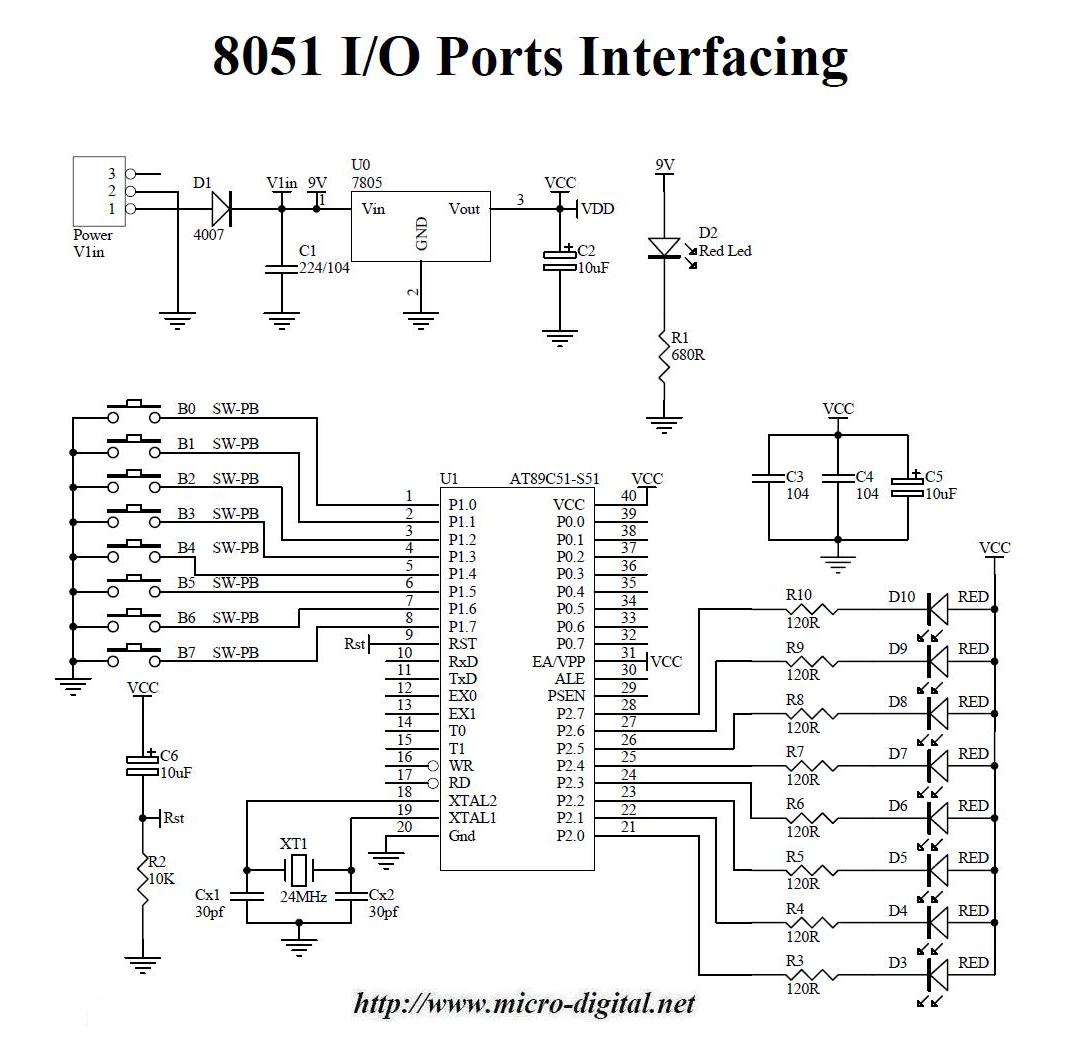
Circuit Diagram
Detail
This example illustrates how can we use I/O ports of an 8051 based microcontroller. In this project I have used one port P1 for input and other port P2 for output. Each of these ports consists of 8 pins that can be accessed and used individually. There are 8 buttons connected to port P1 and 8 LEDs are connected on port P2. When user will press button B0 then LED D3 will toggle (on to off or off to on state). Similarly B1 controls LED D4, B2 controls LED D5 and so on.
For basic operation & components used in an 8051 based microcontroller based systems see
8051 Basic LED Flasher.
Free Downloads
8051-I-O-Ports-Interfacing.zip
Related Projects
8051 To Seven Segment Display Interfacing
Cricket Score Board using 8051 and 7 Segment Display