Description
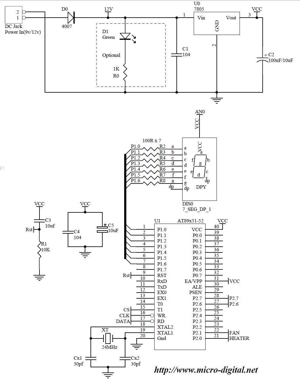
It’s an example project of 7 segment display interfacing to microcontroller 8051.
Diagram
Detail
This project describes how can we connect 7 segment display to 8051 microcontroller. Similarly it can be connected to any other microcontroller like PIC or AVR with modifications in code. Counting from 0 to 9 is displayed on it after some delay. This project also describes how to use 8051 port pins for output and LED drive.
How 7 Segment Works
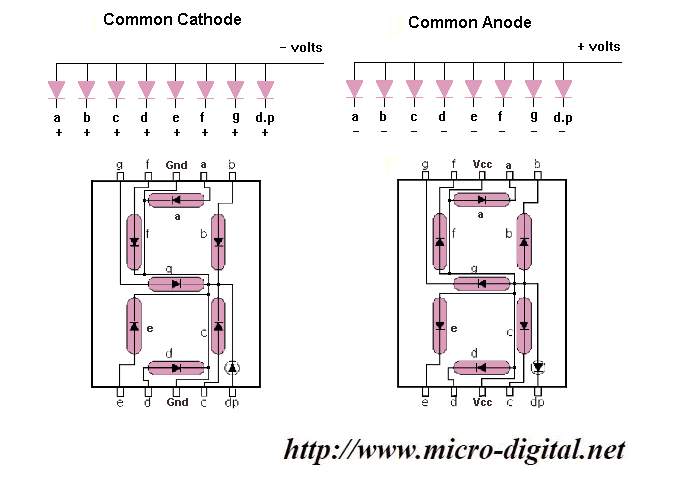
7 segment display consists of 7 segments and a dot. Actually each segment and dot are LEDs (Light Emitting Diodes). Each segment including dot are total 8 LEDs.
 |
| Click to Enlarge |
Light Emitting Diode like an ordinary diode passes current in one direction (forward biased) and block in other (reverse biased) direction. Each LED has 2 pins one for anode and other for cathode. In common anode all anode terminals are connected together to form a common connection and remaining 8 cathodes are provided for negative side supply of individual LED. We connect common wire with positive supply and provide negative supply to appropriate LED segments to switch on and make a specific pattern on the whole display. In common cathode display all pins are opposite to common anode. All cathode terminals are connected to form a common connection and all other 8 pins are anodes. Pin diagram of commonly used seven segment display are given in above figure.
Code
///////////////////////////////////////////////////////////
// Company         : Micro Digital                       //
//                   DAV College Road                    //
//                   Rawalpindi,                         //
//                   Pakistan.                           //
// Programmed By   : Rashid Mehmood                      //
// Project Name    : 8051 To Seven Segment Display       //
// Crystal         : 24.000000 MHz                       //
// Microcontroller : AT89C2051-C51-C52-C55-S2051-S51-S52 //
///////////////////////////////////////////////////////////

// Start of code.

// Header file for AT89x051 microcontrollers.
#include <AT89x051.h>


#define SSeg P1

code const unsigned char RealDigit[10] = {
						0x40, 0x79, 0x24,
						0x30, 0x19, 0x12,
						0x02, 0x78, 0x00,
						0x10
					 };

void  delay(unsigned int del)
{
	// Wait until del is greater zero.
	while(del --);
}

// Displays value (0 to 9) on seven
// segment display.
void Display(unsigned char Value)
{
	if(Value < 10)
		SSeg = RealDigit[Value];
}

void main()
{
	unsigned char Value = 0;
	while(1)
	{
		for(Value = 0; Value < 10; Value ++)
		{
			Display(Value);
			delay(30000);	// Calibrated delay.
		}
	}
}
// End of code.
Related Projects
2-Way Traffic Signal Controller
Cricket Score Board using 8051 and 7 Segment Display
8051 Timer0 As Second Counter On 7 Segment
