Description
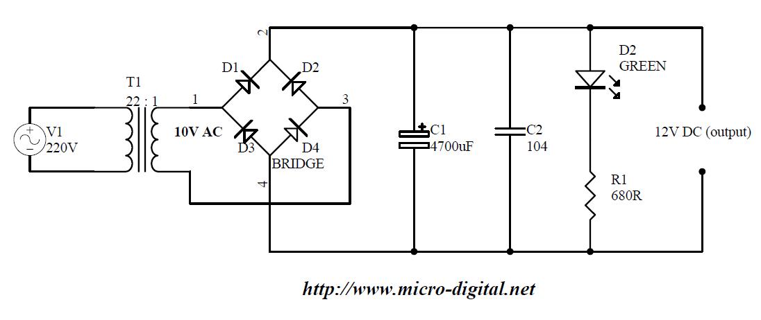
It is 220 volt AC to 12 volt DC full wave rectifier supply.
Diagram
Detail
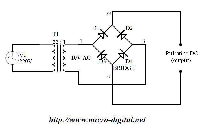
It uses 4 diode to rectify AC voltage. We can understand this circuit by breaking down in parts as follows
 |
| Click to Enlarge |
This is the part that converts AC voltage into pulsating DC by using D1-D4.
 |
| Click to Enlarge |
In this part diode we exclude D2 and D3. Now when transformer output 1 will be positive and output 2 negative during sin wave pulse then diodes D1 and D4 conduct as these are forward biased and positive side is available at D1’s output(labeled as 2) and negative side is available at D4’s output(labeled as 4). When negative voltage is present at output 1 of transformer and positive at output 2 now these diodes will be reversed biased and so will not conduct. And there will be no output due to D1 and D4.
 |
| Click to Enlarge |
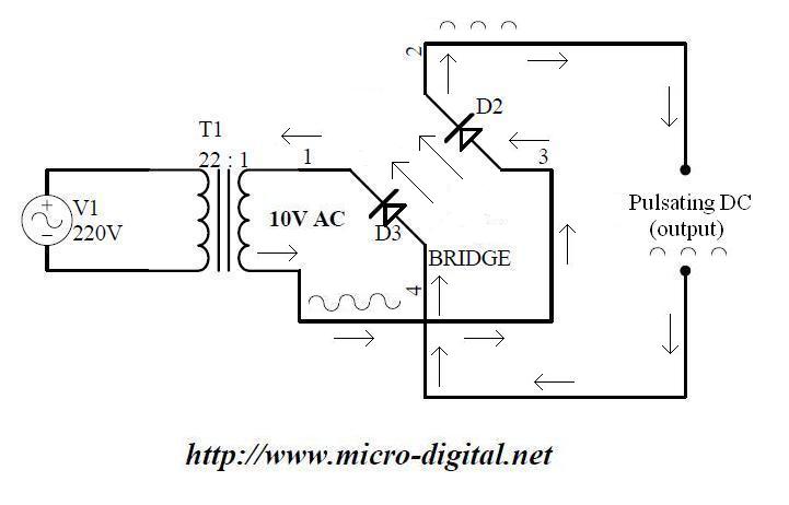
Now we exclude D1, D4 and consider D2, D3 in the circuit. In this way when transformer output 1 will be positive and output 2 negative during sin wave pulse then diodes D2 and D3 will not conduct as these are reversed biased and there will be no output due to these diodes. When negative voltage is present at transformer’s output 1 and positive at output 2 then both diodes D2, D3 will conduct(as these are forward biased) and positive voltage will be available at D2’s output(labeled as 2) and negative voltage will be available at D3’s output(labeled as 4).
Conclusion is that
1) when transformer outputs 1 and 2 go +ve and -ve respectively then diodes pair D1, D2 conducts.
2) when transformer outputs 1 and 2 go -ve and +ve respectively then diodes pair D2, D3 conducts.
3) So one pair conducts during half period (positive) of sin wave and other pair during remaining half period (negative) of sine wave.
4) In both upper cases(1, 2) +ve voltage is present at output labeled 2 and -ve voltage side at output labeled as 4.
 |
| Click to Enlarge |
Now again by combining these 2 parts we can see that these 4 diodes not only provide positive side of sin wave as it is at output(labeled as 2, 4) but also present negative side of sin wave as positive at same output(labeled as 2, 4). So in this way AC signal is converted into DC. But this is not smooth DC but pulsating DC as shown in figure. We will further use capacitors to make these pulsating DC as smooth DC.
 |
| Click to Enlarge |
If we add capacitor C1 at diode output this half wave pulsating DC is stored in this capacitor. At every half cycle this capacitor is charged up and if this energy is not used by load (or in other words there is no path to discharge capacitor) then this capacitor is charged up to almost it’s rated voltage level. Now pulsating effect is removed by the use of this capacitor and smooth DC is obtained at some level. Small capacitor C2 to removes fast pulses of noise. Finally we add an LED D2 and resistor R1 as power on/off indicator. This network also work as to limit charging of capacitor. It provides a path for the discharge of capacitor. For this purpose we usually use a single resistor that is also called blade resistor. It limits capacitor charging to certain level so that load can be saved from over voltage. R1 also limits current through LED D2. We will also upload interesting LED projects for beginners, students and hobbyist.