Introduction
It is an example of Serial ADC0831 To 8051 Microcontroller (AT89C51/AT89S51) Interface. ADC or Analog To Digital Converter reads analog signal level and convert digital/binary value against this level.
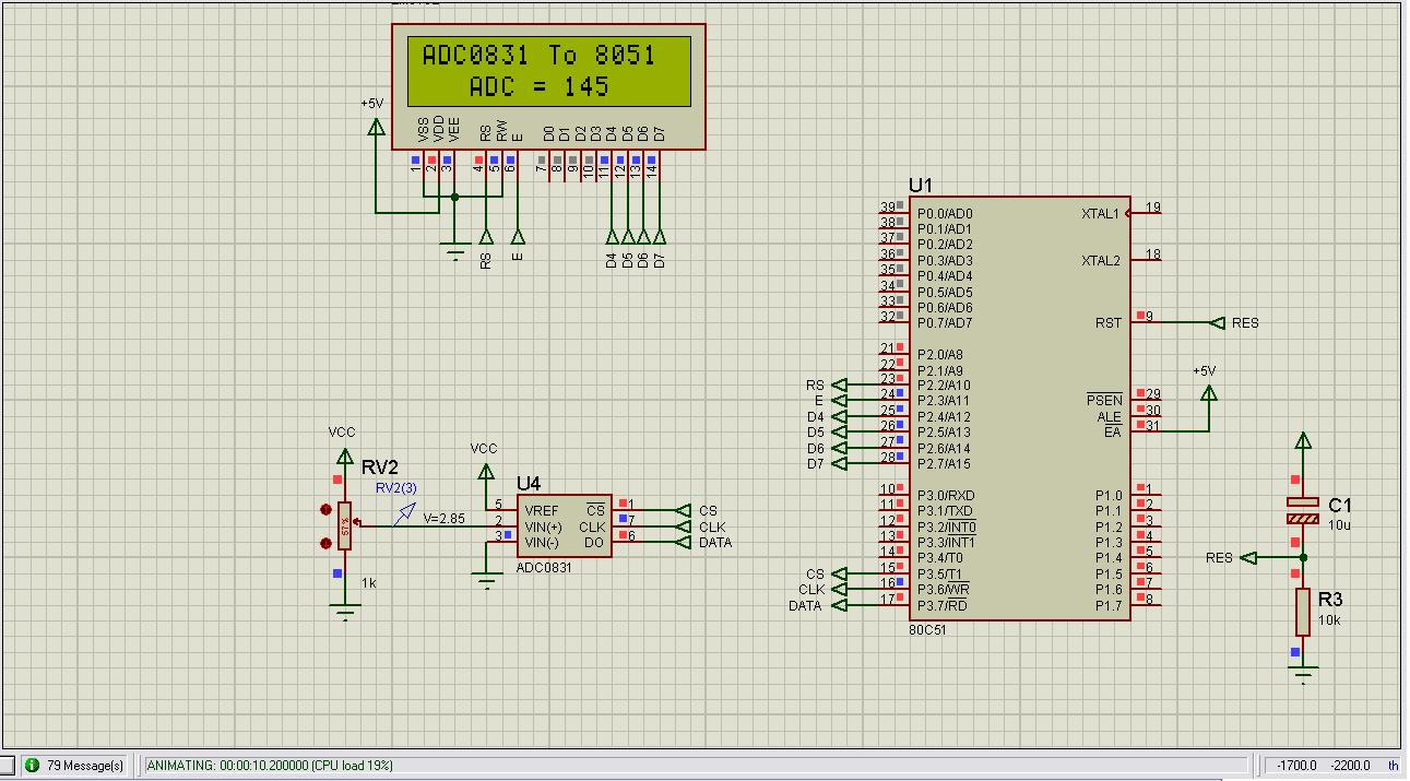
Circuit Diagram
Description
ADC is most widely used and important part in electronics. Most of the time in digital electronics we need to deal or process analog signals. Sensors often present their output in the form of analog signals such as temperature, light, gas and pressure sensors (analog voltage/current). As microcontroller can understand only digital quantities so there is need to convert these analog signal levels to corresponding digital value. This task of analog to digital conversion is performed by Analog To Digital Converter or ADC. Now a days in the market there are so many integrated circuits available in which whole circuit of ADC is integrated. So, ADC is available in a single chip. Some microcontrollers have built-in ADC. But, in case of traditional 8051 microcontroller we need to attach separate ADC chip. Different ADCs have different characteristics. These have different input voltage ranges. Some provide parallel output and some output data in serial stream of bits. These have different resolution say 4, 8, 10, 12 or even 24 bit. High resolution means smaller step and small step means ADC can sense small change in input signal. Let us consider an ADC with 4 bit resolution. It means it’s output may have 2(n) = 2(4) = 16 different levels. consider it’s input voltage range is 0v to 5v. So,
ADC Range = 5v – 0v = 5v
We have used 8 bit, serial output ADC ADC0831 in this project that has only three interface pins to read analog to digital converted value from it. So, less number of pins of microcontroller are used for this purpose and hardware is simple. Software is also simple in which we read ADC result by giving pulses to clock pin of ADC and reading back each bit from data pin of ADC. In parallel output ADC more pins of microcontroller are reserved and hardware becomes complex and so, difficult to troubleshoot.
Remember: Minimum parts used with minimum connections in a circuit make it simple, maintainable and easy to troubleshoot than a circuit with more parts and more connections but sometime it makes the software of microcontroller complex.
As discussed before three pins of ADC are connected to 8051 microcontroller that are
- Chip Select (CS)
- Clock (CK)
- Data (DO)
Remaining pins are
- Vref connected to 5v
- Vin- connected to ground
- Vin+ connected to input analog signal. Here, a wiper pin of variable resistor
Vin- is at 0v and Vref is at 5v so, ADC range is 5v – 0v = 5v. Analog input signal that is to be converted is applied to pin Vin+ of ADC0831. This signal may have level from 0v to 5v range. We have used variable resistor at ADC input just for testing and changing analog input. This change is sensed by microcontroller and is displayed on LCD.
Code Explanation
Here is function to initialize ADC.
1-  void Init_ADC0831()
2-  {
3-     adc_CLK = 0;
4-     adc_CS = 1;
5-     adc_Data = 1;
6-  }
In the above code we have initialized microcontroller pins for ADC, so that ADC is ready for conversion.
Following is the function that reads analog signal level through ADC.
01-  unsigned char ReadADC0831()
02-  {
03-	unsigned char Data;
04-	unsigned char i;
05-	adc_CS = 0;
06-	;;;;;;;
07-	for(i = 0; i < 10; i ++)
08-	{
09-		adc_CLK = 1;;;;;;;;
10-		Data <<= 1;
11-		Data |= adc_DATA;
12-		adc_CLK = 0;;;;;;;;
13-	}
14-	adc_CS = 1;
15-	return Data;
16-  }
At lines 03 we have defined a variable named "Data" in which we will store ADC result coming from ADC. At line 04 a counter variable for "for" loop is defined. At line 05 first we lower down or provide logic 0 to chip select pin of ADC that instruct ADC to start new conversion. After this we delay for some time at line 06 so that ADC complete it's conversion. For loop will be executed 10 times for each bit of ADC result. Actual bits are 8 but according to ADC0831 datasheet we will read 10 bits from ADC and will ignore first 2 bits. At line number 09 we set clock pin of ADC at logic high for bit reading. Line 10 space is made in variable "Data" at least significant bit position. Line 11 reads bit present on data pin of ADC and store this bit in "Data" variable at least significant bit position. After this we lower down ADC clock and cycle for single bit reading is complete. This cycle is repeated 10 times and all ADC result bits are read out of ADC. At line 14 we disable chip select by providing logic high to it and now whole ADC result is present in "Data" variable that we return for further processing.
Following is the main function or entry point of our microcontroller program
01-  void main()
02-  {
03-	unsigned char i;
04-	unsigned char Msg[20];
05-	unsigned int AverageValue;
06-	unsigned char Sample[5] = {0, 0, 0, 0, 0};

07-	InitSystem();
08-	while(1)
09-	{
10-		AverageValue = 0;
11-		for(i = 4; i > 0; i --)
12-		{
13-			Sample[i] = Sample[i - 1];
14-			AverageValue += Sample[i];
15-		}
16-		Sample[0] = ReadADC0831();
17-		AverageValue += Sample[0];
18-		AverageValue /= 5;
19-		sprintf(Msg, "   ADC = %d      \0", AverageValue);
20-		gotoxy_lcd(1, 2);
21-		print_lcd(Msg);
22-	}
23-  }
In this function we perform main task of our program. From line 03 to 06 different variable are defined that will be used next in the function. At line 07 we initialize our system by calling "InitSystem" function. "InitSystem" function initializes ADC, LCD and prints default message "ADC0831 To 8051 " on first line of 16x2 LCD. After this, while loop is executed. From line 10 to 18 we are reading ADC value and calculating 5 point moving average. From line 19 to 21 we are formatting our result in a string "Msg" and showing result on LCD. Steps from line 10 to 21 are repeated until power to microcontroller is applied.
Free Downloads
Interfacing-Serial-ADC0831-To-8051-AT89C51-1.rar with Proteus Simulation