What is Microcontroller

ATMega32-Microcontroller.jpg
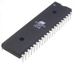
    A microcontroller in simple words is a small computer on a single IC (Integrated Circuit). So it is also called a microcomputer.

    A computer PC or laptop perhaps in front of you consists of different components or parts that are connected together to form a computer system. These parts are microprocessor (CPU), RAM, hard disk, I/O ports, timers etc. Similarly a microcontroller consists of a microprocessor, RAM, Flash or ROM memories (like hard disk in PC), I/O ports, serial ports and timers. These components may vary from one microcontroller to other but some basic parts such as RAM, ROM or Flash memories and ports are essential part of a microcontroller.

    The main difference between a PC/laptop and microcontroller is that PC and laptop are general purpose computer systems while a microcontroller is a specific purpose computer system on a single chip. Usually a single task is dedicated to a microcontroller while general purpose PC runs different type and number of tasks at one time.

    Microcontroller ROM or flash memory is used to store a program (task) that runs on it. RAM is the place where we can store data or declare variables. I/O ports are used to communicate with external world (devices such as ADC, DAC, serial EEPROMs, external memories, LCDs, keypads etc). In addition some microcontroller contain on chip special components such as serial RS232 channel, I2C, ADC, voltage Comparators etc. Usually programming languages used for developing microcontroller program are Assembly, Basic, C. C ++ is also used specially for microcontrollers having resources like program flash and RAM large in amount.

Applications of Microcontrollers

    In our daily life we see more applications around us in which microcontroller is used than a PC. Microcontroller is used in ovens, split units, digital clocks, in our wrist watch, printers, scanners etc.

Types of Microcontroller

    Some of the types of microcontroller are

  1. 8051
  2. AVR
  3. PIC

Tools & Applications for Microcontroller Based Embedded System Development

    These are some of the tools & applications necessary for microcontroller based embedded system development.

  1. Hardware
  2.     A prototyping board, SBC, Trainer or specially designed electronic board that has target microcontroller installed. There are so many other tools that are used in developing these type of electronic boards.

  3. Compiler or Assembler
  4.     Compiler or assembler to write & compile our program. Usually these compiler or assembler generate hex or binary file as output that is finally transferred through programmer or burner device to the target microcontroller.

  5. Programmer or Burner Device
  6.     This is a hardware device that is used to transfer our compiled program or hex file to the target microcontroller.

Categories Uncategorized

8051 4 Digit Electronic Code Lock with LCD and Keypad

Description

It’s an example of 8051 4 Digit Electronic Code Lock with LCD and Keypad.

Circuit Diagram

Detail

This is a simple example of electronic code lock based on 8051 microcontroller. This example project also describes how can we interface 16×2 LCD and keypad. Simple Telephone keypad is used for this project. Initially when system is started “Enter Password ” is displayed on 1st row and user enters password and at each key press a ‘*’ is displayed on screen. This password is of 4 digit length. If after entering 4 digits password matches with predefined password in the program code then system activates the lock relay attached at pin # 0 of port P2 means opens lock and displays user a message that lock is opened. Now on pressing ‘*’ key user can enable lock again. If password is incorrect then system shows invalid password message and does not open the lock. Password for the lock defined in the code is “1234”. If user enters a wrong key and wants to enter password again from start then user can press ‘*’ to re-enter password in the middle.

For detail of LCD interfacing please see 8051 To 16×2 LCD Interfaing.

For basic operation & components used in an 8051 based microcontroller based systems see
8051 Basic LED Flasher.

Free Downloads

8051-4-Digit-Electronic-Code-Lock-with-LCD-and-Keypad.zip
HD44780 Datasheet

Related Projects

8051 Basic LED Flasher

8051 To 16×2 LCD Interfaing

8051 Timer0 As Second Counter On 7 Segment

8051 Digital Clock On 7 Segment (Non Multiplexed)

PC Serial RS232 Port Interface To 16×2 LCD

8051 Calculator with 16×2 LCD and Telephone Keypad

Cricket Score Board using 8051 and 7 Segment Display
More Projects

8051 Calculator with 16×2 LCD and Telephone Keypad

Description

It’s an example of 8051 Calculator with 16×2 LCD and Telephone Keypad.

Circuit Diagram

Detail

This example project describes how can we interface 16×2 LCD and keypad. Simple Telephone keypad is used for this project. Initially when system is started 0 is displayed on 2nd row and right most column. First user enters first operand then select an operation by pressing ‘*’ key once or again and again. When user presses ‘*’ key first multiply operation is displayed on left most upper corner. By pressing ‘*’ key again and again changes operation to be performed and this operation is displayed on upper left corner of the 16×2 LCD. Operation in this version are simply 4 arithmetic operations *,+,- and /. Maximum of 4 digit operand can be entered in this version. After selecting operation user will enter 2nd operand then press ‘#’ key that will perform selected operation and will show result on lower right corner of 16×2 LCD.

For detail of LCD interfacing please see 8051 To 16×2 LCD Interfaing.

For basic operation & components used in an 8051 based microcontroller based systems see
8051 Basic LED Flasher.

Free Downloads

8051-Calculator-with-16×2-LCD-and-Telephone-Keypad.zip
HD44780 Datasheet

Related Projects

8051 Basic LED Flasher

8051 To 16×2 LCD Interfaing

8051 Timer0 As Second Counter On 7 Segment

8051 Digital Clock On 7 Segment (Non Multiplexed)

PC Serial RS232 Port Interface To 16×2 LCD

8051 4 Digit Electronic Code Lock with LCD and Keypad

Cricket Score Board using 8051 and 7 Segment Display
More Projects

Cricket Score Board using 8051 and 7 Segment

Description

It’s an example of Cricket Score Board using 8051 and 7 Segment.

Circuit Diagram

Detail

In this example we have interfaced 7 segment and touch buttons. Initially score of 0 is displayed on seven segments. When user presses button B0 4 is added in the score. When B1 is pressed a score of 6 is added. On pressing B2 1 is decremented from score. And when B3 is pressed 1 is incremented in the score. This score is also updated on seven segment when it is changed. For detail of how can we interface 7 segment displays please see 8051 To 7 Segment Display Interfacing.

For basic operation & components used in an 8051 based microcontroller based systems see
8051 Basic LED Flasher.

Free Downloads

Cricket-Score-Board-using-8051-and-7-Segment.zip

Related Projects

8051 Basic LED Flasher

8051 To 7 Segment Display Interfacing

8051 Timer0 As Second Counter On 7 Segment

8051 Digital Clock On 7 Segment (Non Multiplexed)

8051 Digital Clock On 16×2 LCD

PC Serial RS232 Port Interface To 7 Segment

More Projects

8051 Timer0 as Second Counter on 7 Segment

Description

It’s an example of 8051 Timer0 as Second Counter on 7 Segment.

Circuit Diagram

Detail

In this example we have configured 8051 timer0 for time calculation. There are 4 different modes for timer0 in 8051. We have selected 8 bit auto reload mode. In this mode timer0 hardware is automatically reset upon overflow to a predefined value and again starts counting up. Timer0 counts up 1 after 12 clocks of main system clock oscillator. So if we are using 12 MHz crystal then timer0 input frequency will be 1 MHz.
Here in this project system clock is of 24 MHz and timer0 input clock is 2 MHz. It is reset to value 6 after each overflow. Simply each timer interrupt is occurred after 125 micro seconds. And so in this way if 8 interrupts has occurred then 1 millisecond has passed and if 8000 interrupts has occurred then 1 second has passed and so on. In this way we can calculate hours and minutes also. This time in seconds is updated on 2 digit 7 segment displays regularly. For detail of 7 segment interfacing please see 8051 To 7 Segment Display Interfacing.

For basic operation & components used in an 8051 based microcontroller based systems see
8051 Basic LED Flasher.

Free Downloads

8051-Timer0-as-Second-Counter-on-7-Segment.zip

Related Projects

8051 Basic LED Flasher

8051 To 7 Segment Display Interfacing

Cricket Score Board using 8051 and 7 Segment Display

8051 Digital Clock On 7 Segment (Non Multiplexed)

8051 Digital Clock On 16×2 LCD

PC Serial RS232 Port Interface To 7 Segment

More Projects

8051 Digital Clock On 7 Segment (Non Multiplexed)

Description

It’s an example of 8051 Digital Clock On 7 Segment (Non Multiplexed).

Circuit Diagram

Detail

In this example we have configured 8051 timer0 for time calculation. There are 4 different modes for timer0 in 8051. We have selected 8 bit auto reload mode. In this mode timer0 hardware is automatically reset upon overflow to a predefined value and again starts counting up. Timer0 counts up 1 after 12 clocks of main system clock oscillator. So if we are using 12 MHz crystal then timer0 input frequency will be 1 MHz.
Here in this project system clock is of 24 MHz and timer0 input clock is 2 MHz. It is reset to value 6 after each overflow. Simply each timer interrupt is occurred after 125 micro seconds. And so in this way if 8 interrupts has occurred then 1 millisecond has passed and if 8000 interrupts has occurred then 1 second has passed and so on. In this way we calculate hours and minutes also. This time is updated on 4 digit 7 segment displays regularly. For detail of 7 segment interfacing please see 8051 To 7 Segment Display Interfacing. Buttons are provided for time settings.

For basic operation & components used in an 8051 based microcontroller based systems see
8051 Basic LED Flasher.

Free Downloads

8051-Digital-Clock-On-7-Segment-Non-Multiplexed.zip

Related Projects

8051 Basic LED Flasher

8051 To 7 Segment Display Interfacing

8051 Timer0 As Second Counter On 7 Segment

Cricket Score Board using 8051 and 7 Segment Display

8051 Digital Clock On 16×2 LCD

More Projects

8051 Digital Clock On 16×2 LCD

Description

It’s an example of 8051 Digital Clock On 16×2 LCD.

Circuit Diagram

Detail

In this example we have configured 8051 timer0 for time calculation. There are 4 different modes for timer0 in 8051. We have selected 8 bit auto reload mode. In this mode timer0 hardware is automatically reset upon overflow to a predefined value and again starts counting up. Timer0 counts up 1 after 12 clocks of main system clock oscillator. So if we are using 12 MHz crystal then timer0 input frequency will be 1 MHz.
Here in this project system clock is of 24 MHz and timer0 input clock is 2 MHz. It is reset to value 6 after each overflow. Simply each timer interrupt is occurred after 125 micro seconds. And so in this way if 8 interrupts has occurred then 1 millisecond has passed and if 8000 interrupts has occurred then 1 second has passed and so on. In this way we calculate hours and minutes also. This time is updated on 16×2 LCD regularly. For detail of LCD interfacing please see 8051 To 16×2 LCD Interfaing. Buttons are provided for time settings.

For basic operation & components used in an 8051 based microcontroller based systems see
8051 Basic LED Flasher.

Free Downloads

8051-Digital-Clock-On-16×2-LCD.zip
HD44780 Datasheet

Related Projects

8051 Basic LED Flasher

8051 To 16×2 LCD Interfaing

8051 Timer0 As Second Counter On 7 Segment

8051 Digital Clock On 7 Segment (Non Multiplexed)

PC Serial RS232 Port Interface To 16×2 LCD

More Projects

PC Serial RS232 Port Interface To 16×2 LCD

Description

It’s an example of PC Serial RS232 Port Interface To 16×2 LCD.

Circuit Diagram

Detail

In this example we have interfaced 16X2 LCD with PC serial RS232 port. At PC side we have used a terminal software like hyperterminal that displays data coming from microcontroller and sends user input from keyboard to microcontroller. We can develop our customized software for serial communication on PC side. 8051 microcontroller dipslays data coming from PC on 16×2 LCD. This example also shows that how can we configure and use serial channel of 8051 microcontroller for sending and receiving data to PC.

In this example 8051 microcontroller first displays title information like

PC Serial Port Interface To 16x2 LCD

By    : Micro Digital
Web   : https://www.micro-digital.net
Email : udigital.solutions@gmail.com
Cell  : +92-332-555-8051

User inputs data in the following way

w,1,PC Serial RS232 

In the above example format whole line is comma separated. First character ‘w’ tells microcontroller that it is a write command. After 1st comma ‘1’ represents line number on which we want to write. After 2nd comma “PC Serial RS232 ” is the text to be displayed. So if we summaries above discussion then above line sent to microcontroller tells it that we want to write text “PC Serial RS232 ” on line number 1. Similarly we can write on 2nd line of LCD any text. For example

w,2,16x2 LCD Interface

In above example text is more than 16 characters and so whole text will not be displayed on LCD. Try to send text of not more than 16 characters.

Finally microcontroller shows text on 16×2 LCD according to command line sent. This is an interesting example in which we learn how can we configure 8051 serial channel, communicate with PC, extract data or text and command and then display text on 16×2 LCD.

For basic operation & components used in an 8051 based microcontroller based systems see
8051 Basic LED Flasher.

Free Downloads

PC-Serial-RS232-Port-Interface-To-16×2-LCD.zip
HD44780 Datasheet

Related Projects

8051 Basic LED Flasher

8051 To 16×2 LCD Interfaing

PC Serial RS232 Port Interface To 8051

PC Serial RS232 Port Interface To 7 Segment

8051 Calculator using PC Serial Port

8051 Digital Clock On 16×2 LCD

More Projects

PC Serial RS232 Port Interface To 7 Segment

Description

It’s an example of PC Serial RS232 Port Interface To 7 Segment.

Circuit Diagram

Detail

In this example we have interfaced seven segment display with PC serial RS232 port. In this example we have used PC screen for display and PC keyboard for user input to our 8051 microcontroller like in project 8051 Calculator using PC Serial Port. At PC side we have used a terminal software like hyperterminal that displays data coming from microcontroller and sends user input from keyboard to microcontroller. We can develop our customized software for serial communication on PC side. 8051 microcontroller dipslays data coming from PC on seven segment display. This example also shows that how can we configure and use serial channel of 8051 microcontroller for sending and receiving data to PC.

In this example 8051 microcontroller first displays title information then asks user to press a key from 0 to 9 as seven segment can only display numeric digits. Microcontroller will not display character input other than numeric values from 0 to 9.

PC Serial Port Interface To 7 Segment

By    : Micro Digital
Web   : https://www.micro-digital.net
Email : udigital.solutions@gmail.com
Cell  : +92-332-555-8051

Press a key from 0 to 9

User presses keys in the range from 0 to 9 and microcontroller will just display this value after converting it into seven segment patterns.

This is an interesting example in which we learn how can we configure 8051 serial channel, use PC monitor for microcontroller display, PC keyboard as keyboard attached to microcontroller and use seven segment as numeric digit display.

For basic operation & components used in an 8051 based microcontroller based systems see
8051 Basic LED Flasher.

Free Downloads

PC-Serial-RS232-Port-Interface-To-7-Segment.zip

Related Projects

8051 Basic LED Flasher

PC Serial RS232 Port Interface To 8051

8051 Calculator using PC Serial Port

PC Serial RS232 Port Interface To 16×2 LCD

Cricket Score Board using 8051 and 7 Segment Display

8051 Timer0 As Second Counter On 7 Segment

8051 Digital Clock On 7 Segment (Non Multiplexed)
More Projects

8051 Calculator using PC Serial Port

Description

It’s an example of 8051 Calculator using PC Serial Port.

Circuit Diagram

Detail

This example shows that how can we use PC screen for display and PC keyboard for user input to our 8051 microcontroller. At PC side we use a terminal software like hyperterminal that displays data coming from microcontroller and sends key strokes read to microcontroller. So this makes easy for a new programmer to display and read input from user without interfacing any LCD, seven segment or keypad. This example also shows that how can we configure and use serial channel of 8051 microcontroller for sending and receiving data to PC. In so many projects we need to share data or information to other devices.

In this example 8051 microcontroller first displays title information then asks user to select a choice from given choices like

8051 Calculator using PC Serial Port

By    : Micro Digital
Web   : https://www.micro-digital.net
Email : udigital.solutions@gmail.com
Cell  : +92-332-555-8051

Enter your choice
1) Add
2) Subtract
3) Multiply
4) Divide

User selects a choice by pressing appropriate key from 1 to 4. Then microcontroller asks user to enter 1st number or operand like

Enter 1st number (Max Length 4)
Num1 : 

Then user enters 1st integer value with maximum length 4. For example user enter 124 and presses enter. Then microcontroller asks user for 2nd number

Enter 1st number (Max Length 4)
Num1 : 124
Enter 2nd number (Max Length 4)
Num2 : 

Now user enters 2nd number for example 234 and presses enter.

Enter 1st number (Max Length 4)
Num1 : 124
Enter 2nd number (Max Length 4)
Num2 : 234
Ans  : 358
Press any key to continue...

Finally microcontroller shows answer and asks user to press any key for next calculation. This is an interesting example in which we learn how can we configure 8051 serial channel, use PC monitor for microcontroller display and PC keyboard as keyboard attached to microcontroller.

For basic operation & components used in an 8051 based microcontroller based systems see
8051 Basic LED Flasher.

Free Downloads

8051-Calculator-using-PC-Serial-Port.zip

Related Projects

8051 Basic LED Flasher

PC Serial RS232 Port Interface To 8051

PC Serial RS232 Port Interface To 7 Segment

PC Serial RS232 Port Interface To 16×2 LCD

More Projects